
Senior Project Summary
The CWU R/C Baja car from 2016 suffered broken suspension parts during the competition. The CWU R/C Baja car for 2017 needs a redesigned and optimized suspension so that it will be able to successfully complete the ASME competition. With the suspension handled, Walter Lackey will be taking care of the drivetrain and steering on the car.
The scope of the project is to design and build a 1/10th scale R/C Baja car suspension system that complies with the ASME R/C Baja competition rules. This portion of the project will consist of solely designing a suspension system around the existing chassis that will operate together with my partners steering and drivetrain design.
Design
The design of the suspension system is a symmetrical independent suspension system using transverse leaf springs. Each component of the suspension is symmetrical. This reduces the amount of spare parts needed and reduces the time spent manufacturing parts. Because the differential needs to occupy a portion of the rear of the car, the differential assembly must fit within rear camber link mounts. The hubs are the only other part of the car that will be different front to rear. The rear hubs are fixed and supply power to the wheels while the front hubs must allow for the steering of the car.

Front Suspension

Rear Suspension

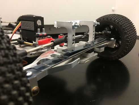
Assembled Car
Analysis
The analyses required for the suspension system included the leaf spring pack spring rate and the strength of the suspension components. The leaf springs were designed per the car weight and desired suspension articulation. The suspension component were designed to withstand airborne impact from two feet or less.
Twisting Force

Vertical Force
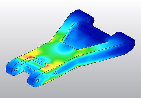
Horizontal Force

Contruction
The suspension components are made up of machined aluminum, 3D printed plastic, and purchased parts. In order to ensure a strong foundation, the suspension mounts are made of 6061 aluminum. Because of the complex design of the control arms, they are 3D printed in ABS plastic. The hubs and camber links were purchased. Upon assembly, the front suspension is assembled, the rear suspension is assembled, and then both sub-assemblies are bolted to the car’s chassis. The drivetrain does not interfere with the suspension so it can be mounted on the chassis at any time.
Drawing Tree
Machining
3D Printing
Testing
In order to ensure that the Baja car will withstand the ASME competition, the car will need to complete a set of tests. For the car to be competitive at the ASME competition, it will need to be able to complete a slalom test, sprint test, and obstacle course test. Each year of the competition, the obstacle course changes so the test course will include as many obstacles as possible to provide the most predictability in the performance of the car. The car will also be subjected to some simple testing to check for suspension durability. Because the car will be competing in the ASME competition, the testing must be done prior to the competition date of April 29th.
Testing Failures
The 3D printed ABS plastic control arms held up well during initial testing. However, arms that were printed at a different time as the first set seemed to to be weaker than. The inconstancy in the material properties and less than satisfactory strength led to the decision to remake the control arms in 6061 aluminum. The control arms now have a safety factor of 18 when compared to the initial design loads. The 3D printed arms were great for prototyping but were not an acceptable final solution.
.jpg)


Results
The car surpassed its expectations in some areas and lacked in others. The car passed the slalom, spring, and articulations test without issues. With the aluminum control arms the car was able to pass the obstacle test as well. The car has not passed the drop test or the spring rate test according to the original requirements. Because the material used for the springs was too thin to reach the 31 pound spring force practically, the car has limitations in its dropping height. The softer spring rate does aid in the control of the car over bumpy surfaces and the car is strong enough to withstand impact of the suspension bottoming out, the conclusion was deemed acceptable.
Spring Rate Issues
The spring rate was supposed to be 31 pounds with a parameter between 27 and 34 pounds. The test resulted in a spring rate of five pounds which was way outside of the parameter. There are a couple of factors that contribute to the failure of this the Spring Rate Test. As mentioned before, the spring rate was calculated using an equation that had unknown assumptions. This equation was set up for the design of leaf springs but was procured from an unreliable source. When the spring rate was calculated using simple beam deflection for one leaf spring, the resulting values mimicked the test values for one leaf spring. Another issue that contributed to the failure of the test is the way in which the leaf springs deflect. The leaf springs deflect more than anticipated between the leafs. This results in a spring that is softer than it is calculated to be.
Budget & Schedule
Budget
The total cost for the project is quite low. The budget is set at $200, has not yet been reached. Many parts have been reused from previous CWU Baja cars, which keeps the budget low. Some parts have also been free such as the scrap aluminum used for the suspension mounts. The bulk of the cost will be in fasteners and bulk materials for fabrication and construction. All parts and materials are under $50, excluding the 3D printing cost. The 3D printing cost has not been totaled yet so those costs are not factored it. The total cost for the printing will likely be under $150 so the budget is on course. At the moment, all funding will be personal money. Labor costs will be free unless there is a change in manufacturing methods for the suspension components. Changes such as waterjet cutting will drive up project costs. The proposed budget and parts breakdown is available in the report under Appendix D on Table D1.
Schedule
The schedule can be seen in Appendix E as Figure E1. The schedule includes every step needed to complete the entire project. The schedule begins with the proposal, then outlines the construction of the project, and is followed by the testing of the car. Each heading has an expected completion time and an actual completion time. The completed portions of the project have the actual completion times filled out. Each section includes a total time of completion. The Gantt Chart is included in the report under Appendix E as Figure E2. The Gantt Chart shows the timeline for the main headings of the project. It illustrates the start date and the completion of each of the headings.
